Monday, January 21, 2013
weekly timer
 |
| electronic weekly timer |
When we want to control the exact time of activation and function of a power consumption that is repeated every week we can use the weekly timer. Similarly there daily timer and rarely monthly timer.
A simple weekly electronic timer shown in the photo.
The minimum period you can turn depends on the individual model. in one in photograph is one minute.
There are also mechanic timer that gets its name from the programming way, with teeth that get on or off and each tooth has a specific duration eg 15 minutes.
The standard is to contain an internal battery to keep time if it drops the power supply.
Bottom right, in this photography is to provide suply at 230 volts and below left is the contact we use for control. The supply voltage varied depending on the model and is electrically isolated (galvanically isolated) from contact consumption.
If we have high power consumption is better to put intermediate relays. The timer in this case controls the armature of the relay and the relay controls the consumption.
Necessarily need intermediate relay if consumption is three phase or consisting of more than two single-phase differential phase.
There are popular in the market timers who come directly to schuko socket and control the consumption of their own place in the socket - outlet.

Double recycle time relay
 |
| Double recycle time relay |
Sometimes we need to automate one electric - electronic element that makes continuous opening and closing his mark, like a flash, or something similar.
The double time doing just that.
It has, as shown in the photo, two positions for setting the time that the internal relay or transistor, is armed and the other adjust the time that the internal relay is deactivated.
Usually the range is independent for each time, e.g. may function to ON (armed) to select the region from 1 to 10 hours and for operation OFF (off) 0.1 to 1 second. In any case and for as long a duration is armed, the two times continuously rotated simultaneously with the contact.
The operating voltage of the double time is similar to that of other components used in automation. Common values ​​are 230 volts AC and 24 vollts AC or DC.
In the market there are times that can work in all standard voltages (the same) or multifunction time not only double but they and many other time functions.
The Timers that are more accurate but they are basically more expensive.
The numbers usually used for contact operation is 15 (for the common node) and 16/18 for open or closed contact, while arming them A1 and A2 (or B) depending on the manufacturer and the voltage operation.
Sunday, January 20, 2013
inverter circuit
 |
| inverter circuit |
The three-phase motor, which is the first choice for many applications have their speed directly dependent on the frequency of the power supply.
Everywhere on earth, the frequency is determined and fixed by the provider and can not be selected
The only satisfactory way to test the speed is via inverter.
The inverter "reverses" (invert) the voltage, makes controlled AC rms and frequency.
The technique of creating alternating voltage constant, which is usually selected by the manufacturers of inverters,is the PWM (Phase Width Modulation)
The DC voltage they need is making from the alternating supply with single-phase or three-phase bridge rectifier.
The basic design operating an inverter shown.
As switches data, T1 to T6, used fast response power transistors. The diodes D1 to D6, which are free-flow passages are also fast response and is to protect the transistor.
 |
| Schneider-phase inverter |
There are in-phase inverter market is small triphasic motors, three-phase inverter and intended for larger motors.
The characterization of single phase or three phase, indicating loading it, if we have a single-phase input voltage of 230 volts for Greece, or three-phase 400 volts. And also identify the maximum rms value of the output voltage can give, ie 230 volts to 400 volts single phase and three phase for.
The operating parameters of the inverter varies with the brand, the size of their power and capabilities and "passed" to memory by either the panel with the display having, or several models, through H / Y.
The main parameters include acceleration time (how many seconds from startup reaches the selected speed - frequency), time delay (in number of seconds the command will stop reaches the minimum allowable frequency before stopping), the minimum and maximum operating frequency , setting a maximum output current and thermal power.
 |
| Under the lid of inverter |
Because of the way creating the alternating voltage, fragmentation of continuous electronic switches with large frequencies (approximately 5 to 20 KHz selected via parameter) there are unwanted harmonic frequencies as they are called, which are multiples of the frequency of fragmentation.
In motor controlled by inverter there is the disadvantage of unnecessary "movement" of these harmonic currents that generate unwanted heat pipes and can in some cases the energy waste is measurable and relatively large example in large industries.
The cable from the inverter to the motor must be grounded conductive mantle, that is, blentaz, as they say, because the frequencies of the harmonics are such as electromagnetic pulse transmitted by "parasites" in adjacent circuits and certainly not good for man .
 |
| Three-phase inverter yaskawa brand |
The motor controlled by inverter must have good ventilation at low speeds because there is adequate ventilation by their own cooling fans.
If it works then at low revs must enter separate cooling fan. There are specially designed motor with higher heat dissipation surfaces specifically to be driven by inverter.
Air conditioners with inverter control the speed of the compressor motor freon according to the temperature setting and not the maximum speed of the motor, as it would be if they had the inverter, thus achieving a better result and economy.
Wednesday, January 16, 2013
Example of OMRON CP1E PLC programming using CX programmer
The PLC of OMRON is generally consistent with many capabilities.It has many models with many variations that cover a variety of needs.
The main method is by programming with LADDER language , computer and program CX - programmer, series programs CX - one, sold separately.
DEMO version of the software is free for download and use.
A small model is the OMRON CP1E associated with the H / PC via a single USB cable from where the example of this suspension.
The 0.00 is the word 0 bit 0 and is always input while 100.01 is bit 1 of word 100 which is always output.
In the example the logical process tells to the PLC:
((if the input I 0.00 is 1 or the input I 0.02 is 0) and the input I 0.01 is 1 then the output Q 100.01 becomes 1)
(If input I 0.03 comes 1 the output Q 100.00 becomes restraint 1 (Set))
(If input I 0.04 comes 1 the output Q 100.00 is 0 (Reset))
Continue read[...]
The main method is by programming with LADDER language , computer and program CX - programmer, series programs CX - one, sold separately.
DEMO version of the software is free for download and use.
A small model is the OMRON CP1E associated with the H / PC via a single USB cable from where the example of this suspension.
 |
Simple example program for the Omron PLC CP1E with Ladder |
The 0.00 is the word 0 bit 0 and is always input while 100.01 is bit 1 of word 100 which is always output.
In the example the logical process tells to the PLC:
((if the input I 0.00 is 1 or the input I 0.02 is 0) and the input I 0.01 is 1 then the output Q 100.01 becomes 1)
(If input I 0.03 comes 1 the output Q 100.00 becomes restraint 1 (Set))
(If input I 0.04 comes 1 the output Q 100.00 is 0 (Reset))
 |
| end of the program |
High voltage transformer
 |
| High voltage transformer 22000 Volts |
This particular three-phase AC power transformer of the photograph is 800 KVA, 1155 A reference to the output stage. The usual connectivity is the triangle at the entrance of the high voltage and star at the output (400 Volts).
Within the slices, that look like radiators, oil is there for both insulation and cooling the elements of the transformer.
The black wires that go down is the additional grounding that goes on during work on the transformer or the surrounding area.
 |
| Body temperature of the transformer |
The left indicator is the actual temperature.
The red arrow (right) shows the temperature above which thetransformer for safety reasons, stops the operation of "throwing" the switch that controls the supply voltage. If thetemperature exceeds a reference to the black arrow (here is the middle) sounds a warning siren.
The adapter also comes off for low oil level or multiple air bubbles in the oil.
Sunday, January 13, 2013
Relay
 |
| relay |
 |
| relays coil |
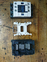
At the end of the movable iron part have adapted one or usually more electrical contacts, insulated from one another as well as to the electromagnet.
As the voltage across the coil exists, there is magnetism. When you stop the voltage, a spring that has meanwhile compressed is geting back the electrical contacts.
 |
| parts of one relay |
 |
| relays label |
There is great variety in the number of contacts, size and operating voltages of the coil.
There relay specially constructed to withstand more effectively in resistive (eg, resistance heating), inductive (eg motors) or capacitive load (eg compensation capacitors)
A form of relay common in industry and in control of three phase electric motors is that of photographs.
 |
| relays contact |
 |
| Smal finder relays |
Problem dysfunction can occur after heavy use or poor choice of power or damage to load - consumption control. Usually the power contacts are those most frequently damaged.
The ends of the coil Names as A1 and A2 in the majority of manufacturers relay.
 |
| relays contact |
 |
| Electronic board with relays |
The contacts withstand current for motors 5,5 KWatts called power contacts and is three Normally Open, one for each phase.
The remaining contacts in the auxiliary relay are designed for low current and are from one to six. They also called contacts or auxiliary automation.
Usually an auxiliary NO is standard in main body of the relay, and if we want more NO or NC we must to buy separately and add them to the socket on the relay and are usually clipped
Saturday, January 12, 2013
Program for the siemens LOGO! Fill control logosoft
 |
| FBD chart. Click to enlarge |
Controls and rejects with the help of an external shift register, the bad products.
If there are three consecutive defects products the machine stops.
The check is for both weighing and a lack of product.
J3: Making on off the fill control
I4: Making on off of the weighing control
I6: mark the exact time to be tested .
I7: Signal for lack of product
I8: Signal from the mechanism of weight trashy product
Q2: Signal to the shift register to discard the product.
Subscribe to:
Posts (Atom)