Wednesday, April 10, 2013
High Power Car Battary Eliminator
To operate car audio (or video) system from household 230V AC mains supply, you need a DC adaptor. DC adaptors available in the market are generally costly and supply an unregulated DC. To overcome these problems, an economical and reliable circuit of a high-power, regulated DC adaptor using reasonably low number of components is presented here. Transformer X1 steps down 230V AC mains supply to around 30V AC, which is then rectified by a bridge rectifier comprising 5406 rectifier diodes D1 through D4. The rectified pulsating DC is smoothed by two 4700μF filter capacitors C1 and C2. The next part of the circuit is a seriestransistor regulator circuit realised using high-power transistor 2N3773 (T1).

Fixed-base reference for the transistor is taken from the output pin of 3-pin regulator IC1 (LM 7806). The normal output of IC1 is raised to about 13.8 volts by suitably biasing its common terminal by components ZD1 and LED1. This simple arrangement provides good, stable voltcuit age reference at a low cost. LED1 also works as an output indicator.Finally, a crowbar-type protection circuit is added. If the output voltage exceeds 15V due to some reason such as component failure, the SCR fires because of the breakdown of zener ZD2. Once SCR fires, it presents a short-circuit across the unregulated DC supply, resulting in the blowing of fuse F1 instantly. This offers guaranteed protection to the equipment connected and to the circuit itself.

This circuit can be assembled using a small general-purpose PCB. A goodquality heat-sink is required for transistor T1. Enclose the complete circuit in a readymade big adaptor cabinet as shown in the figure.
Source: http://www.ecircuitslab.com/2011/09/high-power-car-battary-eliminator.html
Saturday, April 6, 2013
Suzuki Cultusswift Wiring Diagram Electrical Schematics1990

Headlight Switch Diagram 2010 Jeep Wrangler Wiring Diagram Headlight.

About Toyota Celica Wiring Diagram And Electrical System Here.

Audi 80 90 Electric Mirror Wiring Diagram Circuit Schematic.

Suzuki Cultus Swift Wiring Diagram And Electrical Schematics 1990.

1987 Bmw E30 M3 Electrical Wiring Diagram Cable Harness Routing And.

1998 Nissan Maxima Wiring Diagram And Electrical System Circuit.

Nissan Terrano Electrical Wiring Diagram And Harness Circuit.

Toyota Paseo Wiring Diagram Galant Wiring Diagram Detail Electrical.

Toyota Tacoma Electrical Wiring Diagram Png.

Index Of Content How To Use This Manual Wiring And Electric Parts.
AT89C2051 microcontroller circuit
Real time controller AT89C2051
Real time controller is a device used to exercise control over household device continuously ongoing and scheduled. The series of Real Time Controllers with microcontroller AT89C2051 which dituls in this article is a tool that can do that serve targeted. The series of Real Time Controller with Microcontroller AT89C2051 Atmel AT89C2051 uses a data processor and controller as device installed.
In the application directly devices requires a separate interface from a wide range of Real Time Controllers with this AT89C2051 microcontroller. When will connect the device with the AC power source to use interface optocoupler (MOC) or solid state relay. Devices that can be connected with the series of Real Time Controller with Microcontroller AT89C2051 include lights, water machines, fans, electronic gate. The series of Real Time Controllers with this AT89C2051 microcontroller to control a height of water level, controlling the flame lights the scheduled SCARA and censored.

Specifications Series Real Time Controller with AT89C2051 Microcontroller
The series of Real Time Controller with Microcontroller AT89C2051 uses a computer to perform serial communication settings via computer. The series of Real Time Controller with Microcontroller AT89C2051 has 6 units of output channels that can be independently controlled depending on the program induced in the tool. Output in the series of Real Time Controller with AT89C2051 microcontroller requires an interface to deal with equipment that will be in control.
Tuesday, April 2, 2013
Direction Sensor CMPS03
CMPS03 Compass Module Overview
Compass is a tool for navigation for a direction, a direction in this article referred to is the magnetic module CMPS03 Compas. Magnetic Compass Module CMPS03 often used in making robots in the contest.
Magnetic Compass Module Functions in the contest CMPS03 usually to provide a reference where the robots are in position and lead anywhere, then the position and direction provided by the Magnetic Compass Module reference sebgai CMPS03 the next robot motion. Magnetic Compass Module uses I2C data communication lines to mirokontroler. With adalanya I2C data communication lines from this CMPS03 this module can be connected directly to a microcontroller that suport with I2C data communication channels such as AVR ATMega. Magnetic Compass Module CMPS03 require 5 V voltage with 15mA current.
Magnetic Compass Module Functions in the contest CMPS03 usually to provide a reference where the robots are in position and lead anywhere, then the position and direction provided by the Magnetic Compass Module reference sebgai CMPS03 the next robot motion. Magnetic Compass Module uses I2C data communication lines to mirokontroler. With adalanya I2C data communication lines from this CMPS03 this module can be connected directly to a microcontroller that suport with I2C data communication channels such as AVR ATMega. Magnetic Compass Module CMPS03 require 5 V voltage with 15mA current.
 |
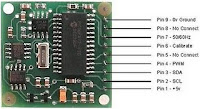
| CMPS03 Circuit Diagram |
Because the module using I2C Magnetic Compass CMPS03 we can use 5 lines are:
VCC + 5 V on pin 1
SCL with Pull Up resistor 10 K
SDA with Pull Up resistor 10 K
Calibrate the PIN associated with micro switch 6
Ground on PIN9
Subscribe to:
Posts (Atom)