Monday, May 13, 2013
Telephone call Voice Changer
Although this kind of voice effect can be obtained by means of some audio computer programs, a few correspondents required a stand-alone device, featuring microphone input and line or loudspeaker outputs.This design fulfills these requirements by means of a variable gain microphone preamplifier built around IC1A, a variable steep Wien-bridge pass-band filter centered at about 1KHz provided by IC1B and an audio amplifier chip (IC2) driving the loudspeaker.
Continue read[...]

Sunday, May 5, 2013
SRPP Headphone Amplifier Circuit Diagram
Mention valve amplifiers and many designers go depressive instantly over the thought of a suitable output transformer. The part will be in the history books forever as esoteric, bulky and expensive because, it says, it is designed and manufactured for a specific valve constellation and output power. There exist thick books on valve output transformers, as well as gurus lecturing on them and winding them by hand. However, with some concessions to distortion (but keeping a lot of money in your pocket) a circuit configuration known as SRPP (series regulated push-pull) allows a low-power valve amplifier to be built that does not require the infamous output transformer. SRPP is normally used for preamplifier stages only, employing two triodes in what looks like a cascade arrangement.
SRPP Headphone Amplifier Circuit Diagram

SRPP Headphone Amplifier Circuit Diagram

Here we propose the use of two EL84 (6BQ5) power pentodes in triode SRPP configuration. The reasons for using the EL84 (6CA5) are mainly that it’s cheap, widely available and forgiving of the odd overload condition. Here, two of these valves are SRPP’d into an amplifier that’s sure to reproduce that ‘warm thermionic sound’ so much in demand these days.
Before describing the circuit operation, it must be mentioned that construction of this circuit must not be attempted unless you have experience in working with valves at high voltages, or can rely on the advice and assistance of an ‘old hand’. As a safety measure, two anti-series connected zener diodes are f it ted at the amplifier output. These devices protect the output (i.e. your head-phones and ears) against possibly dangerous voltages at switch-on,or when output capacitor C3 breaks down.
The power supply is dimensioned for two channels, i.e. a stereo version of the amplifier. The values in brackets are for Elektor readers on 120 VAC power. Note the doubled values of fuses F1 and F3 in the AC primary circuits. The PSU is a conventional design, possibly with the exception of the 6.3 V heater voltage being raised to a level of about +80 V through voltage divider R7-R8. This is done to prevent exceeding the maximum cathode-heater voltage specified for the EL84 (6CA5). R6 is a bleeder resistor emptying the reservoir capacitors C8 and C9 in a quick but control-led manner when the amplifier is switched off. Rectifier diodes D3–D6 each have an anti-rattle capacitor across them.
In the amplifier, assuming the valves used have roughly the same emission, the half-voltage level of about +145 V exists at the junction of the anode of V1 and the control grid of V2. The SRPP is no exception to the rule that high quality, (preferably) new capacitors are essential not just for reproducibility and sound fidelity, but also for safety.
Before describing the circuit operation, it must be mentioned that construction of this circuit must not be attempted unless you have experience in working with valves at high voltages, or can rely on the advice and assistance of an ‘old hand’. As a safety measure, two anti-series connected zener diodes are f it ted at the amplifier output. These devices protect the output (i.e. your head-phones and ears) against possibly dangerous voltages at switch-on,or when output capacitor C3 breaks down.
The power supply is dimensioned for two channels, i.e. a stereo version of the amplifier. The values in brackets are for Elektor readers on 120 VAC power. Note the doubled values of fuses F1 and F3 in the AC primary circuits. The PSU is a conventional design, possibly with the exception of the 6.3 V heater voltage being raised to a level of about +80 V through voltage divider R7-R8. This is done to prevent exceeding the maximum cathode-heater voltage specified for the EL84 (6CA5). R6 is a bleeder resistor emptying the reservoir capacitors C8 and C9 in a quick but control-led manner when the amplifier is switched off. Rectifier diodes D3–D6 each have an anti-rattle capacitor across them.
In the amplifier, assuming the valves used have roughly the same emission, the half-voltage level of about +145 V exists at the junction of the anode of V1 and the control grid of V2. The SRPP is no exception to the rule that high quality, (preferably) new capacitors are essential not just for reproducibility and sound fidelity, but also for safety.
Wednesday, May 1, 2013
12V Powered 12V Lead Acid Battery Charger with Indicator
Some
of you might wonder why a charger is needed at all, to charge a 12
Volt battery from a 12 Volt source! Well, firstly the "12 Volt" source
will typically vary anywhere from 11 Volt to 15 Volt, and then a battery
needs a controlled charge current and voltage, which cannot result
from connecting it directly to a voltage source. The charger described
here is intended for charging small 12 Volt lead acid batteries, such
as the gelled or AGM batteries of capacities between about 2 and 10 Ah,
using a cars electrical system as power source, regardless of whether
the car engine is running or not. I built this charger many years ago, I
think I was still in school back then. On request of a reader of my
web site, Im publishing it now, despite being a rather crude circuit.

It works, it is uncritical to build, and uses only easy-to-find parts, so it has something in its favor. The downside is mainly the low efficiency: This charger wastes about as much power as it puts into the battery. The charger consists of two stages: The first is a capacitive voltage doubler, which uses a 555 timer IC driving a pair of transistors connected as emitter followers, which in turn drive the voltage doubler proper. The doubler has power resistors built in, which limit the charging current. The second stage is a voltage regulator, using a 7815 regulator IC. Its output is applied to the battery via a diode, which prevents reverse current and also lowers the voltage a bit.

The resulting charge voltage is about 14.4V, which is fine for charging a gelled or AGM battery to full charge, but is too high as a trickle charger, so dont leave this charger permanently connected to a battery. If you would like to do just that, then add a second diode in series with D3! There is a LED connected as a charge indicator. It will light when the charge current is higher than about 150mA. The maximum charge current will be roughly 400mA. There is an auxiliary output, that provides about 20V at no load (depending on input voltage), and comes down as the load increases. I included this for charging 12V, 4Ah NiCd packs, which require just a limited current but not a limited voltage for charging.

Note that if the charge output is short-circuited, the overcurrent protection of U2 will kick in, but the current is still high enough to damage the diodes, if it lasts. So, dont short the output! If instead you short the auxiliary output, the fuse should blow. I built this charger into a little homemade aluminum sheet enclosure, using dead-bug construction style. Not very tidy, but it works. Note the long leads on the power resistors. They are necessary, because with shorter leads the resistors will unsolder themselves, as they get pretty hot! The transistors and the regulator IC are bolted to the case, which serves as heat sink. The transistors dont heat up very much, but the IC does.

It works, it is uncritical to build, and uses only easy-to-find parts, so it has something in its favor. The downside is mainly the low efficiency: This charger wastes about as much power as it puts into the battery. The charger consists of two stages: The first is a capacitive voltage doubler, which uses a 555 timer IC driving a pair of transistors connected as emitter followers, which in turn drive the voltage doubler proper. The doubler has power resistors built in, which limit the charging current. The second stage is a voltage regulator, using a 7815 regulator IC. Its output is applied to the battery via a diode, which prevents reverse current and also lowers the voltage a bit.

The resulting charge voltage is about 14.4V, which is fine for charging a gelled or AGM battery to full charge, but is too high as a trickle charger, so dont leave this charger permanently connected to a battery. If you would like to do just that, then add a second diode in series with D3! There is a LED connected as a charge indicator. It will light when the charge current is higher than about 150mA. The maximum charge current will be roughly 400mA. There is an auxiliary output, that provides about 20V at no load (depending on input voltage), and comes down as the load increases. I included this for charging 12V, 4Ah NiCd packs, which require just a limited current but not a limited voltage for charging.

Note that if the charge output is short-circuited, the overcurrent protection of U2 will kick in, but the current is still high enough to damage the diodes, if it lasts. So, dont short the output! If instead you short the auxiliary output, the fuse should blow. I built this charger into a little homemade aluminum sheet enclosure, using dead-bug construction style. Not very tidy, but it works. Note the long leads on the power resistors. They are necessary, because with shorter leads the resistors will unsolder themselves, as they get pretty hot! The transistors and the regulator IC are bolted to the case, which serves as heat sink. The transistors dont heat up very much, but the IC does.
Source: Homo Ludens
Wednesday, April 10, 2013
High Power Car Battary Eliminator
To operate car audio (or video) system from household 230V AC mains supply, you need a DC adaptor. DC adaptors available in the market are generally costly and supply an unregulated DC. To overcome these problems, an economical and reliable circuit of a high-power, regulated DC adaptor using reasonably low number of components is presented here. Transformer X1 steps down 230V AC mains supply to around 30V AC, which is then rectified by a bridge rectifier comprising 5406 rectifier diodes D1 through D4. The rectified pulsating DC is smoothed by two 4700μF filter capacitors C1 and C2. The next part of the circuit is a seriestransistor regulator circuit realised using high-power transistor 2N3773 (T1).

Fixed-base reference for the transistor is taken from the output pin of 3-pin regulator IC1 (LM 7806). The normal output of IC1 is raised to about 13.8 volts by suitably biasing its common terminal by components ZD1 and LED1. This simple arrangement provides good, stable voltcuit age reference at a low cost. LED1 also works as an output indicator.Finally, a crowbar-type protection circuit is added. If the output voltage exceeds 15V due to some reason such as component failure, the SCR fires because of the breakdown of zener ZD2. Once SCR fires, it presents a short-circuit across the unregulated DC supply, resulting in the blowing of fuse F1 instantly. This offers guaranteed protection to the equipment connected and to the circuit itself.

This circuit can be assembled using a small general-purpose PCB. A goodquality heat-sink is required for transistor T1. Enclose the complete circuit in a readymade big adaptor cabinet as shown in the figure.
Source: http://www.ecircuitslab.com/2011/09/high-power-car-battary-eliminator.html
Saturday, April 6, 2013
Suzuki Cultusswift Wiring Diagram Electrical Schematics1990

Headlight Switch Diagram 2010 Jeep Wrangler Wiring Diagram Headlight.

About Toyota Celica Wiring Diagram And Electrical System Here.

Audi 80 90 Electric Mirror Wiring Diagram Circuit Schematic.

Suzuki Cultus Swift Wiring Diagram And Electrical Schematics 1990.

1987 Bmw E30 M3 Electrical Wiring Diagram Cable Harness Routing And.

1998 Nissan Maxima Wiring Diagram And Electrical System Circuit.

Nissan Terrano Electrical Wiring Diagram And Harness Circuit.

Toyota Paseo Wiring Diagram Galant Wiring Diagram Detail Electrical.

Toyota Tacoma Electrical Wiring Diagram Png.

Index Of Content How To Use This Manual Wiring And Electric Parts.
AT89C2051 microcontroller circuit
Real time controller AT89C2051
Real time controller is a device used to exercise control over household device continuously ongoing and scheduled. The series of Real Time Controllers with microcontroller AT89C2051 which dituls in this article is a tool that can do that serve targeted. The series of Real Time Controller with Microcontroller AT89C2051 Atmel AT89C2051 uses a data processor and controller as device installed.
In the application directly devices requires a separate interface from a wide range of Real Time Controllers with this AT89C2051 microcontroller. When will connect the device with the AC power source to use interface optocoupler (MOC) or solid state relay. Devices that can be connected with the series of Real Time Controller with Microcontroller AT89C2051 include lights, water machines, fans, electronic gate. The series of Real Time Controllers with this AT89C2051 microcontroller to control a height of water level, controlling the flame lights the scheduled SCARA and censored.

Specifications Series Real Time Controller with AT89C2051 Microcontroller
The series of Real Time Controller with Microcontroller AT89C2051 uses a computer to perform serial communication settings via computer. The series of Real Time Controller with Microcontroller AT89C2051 has 6 units of output channels that can be independently controlled depending on the program induced in the tool. Output in the series of Real Time Controller with AT89C2051 microcontroller requires an interface to deal with equipment that will be in control.
Tuesday, April 2, 2013
Direction Sensor CMPS03
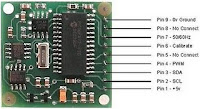
CMPS03 Compass Module Overview
Compass is a tool for navigation for a direction, a direction in this article referred to is the magnetic module CMPS03 Compas. Magnetic Compass Module CMPS03 often used in making robots in the contest.
Magnetic Compass Module Functions in the contest CMPS03 usually to provide a reference where the robots are in position and lead anywhere, then the position and direction provided by the Magnetic Compass Module reference sebgai CMPS03 the next robot motion. Magnetic Compass Module uses I2C data communication lines to mirokontroler. With adalanya I2C data communication lines from this CMPS03 this module can be connected directly to a microcontroller that suport with I2C data communication channels such as AVR ATMega. Magnetic Compass Module CMPS03 require 5 V voltage with 15mA current.
Magnetic Compass Module Functions in the contest CMPS03 usually to provide a reference where the robots are in position and lead anywhere, then the position and direction provided by the Magnetic Compass Module reference sebgai CMPS03 the next robot motion. Magnetic Compass Module uses I2C data communication lines to mirokontroler. With adalanya I2C data communication lines from this CMPS03 this module can be connected directly to a microcontroller that suport with I2C data communication channels such as AVR ATMega. Magnetic Compass Module CMPS03 require 5 V voltage with 15mA current.
 |
| CMPS03 Circuit Diagram |
Because the module using I2C Magnetic Compass CMPS03 we can use 5 lines are:
VCC + 5 V on pin 1
SCL with Pull Up resistor 10 K
SDA with Pull Up resistor 10 K
Calibrate the PIN associated with micro switch 6
Ground on PIN9
Subscribe to:
Posts (Atom)