Wednesday, September 28, 2011
LM2758 FLASH LED DRIVER EVALUATION BOARD ELECTRONIC DIAGRAM
LM2758 FLASH LED DRIVER EVALUATION BOARD ELECTRONIC DIAGRAM
To startup the Evaluation board, set the EN1 jumper and EN2 jumper to the “OFF” position, apply power to the board, and then move the EN jumper(s) to the “ON” position. This is the expected startup operation in the typical application where VIN is tied to a voltage rail and the EN pins are controlled via logic signal.
Labels:
BOARD,
BOARD CIRCUIT,
BOARD DIAGRAM,
BOARD SCHEMATIC,
FLASH LED,
FLASH LED CIRCUIT,
FLASH LED DIAGRAM,
FLASH LED SCHEMATIC,
LED,
RANGKAIAN FLASH LED,
SKEMA FLASH LED
LED BACKLIGHTING SOLUTION WITH LM3430 and LM3432 ELECTRONIC DIAGRAM
LED BACKLIGHTING SOLUTION WITH LM3430 and LM3432 ELECTRONIC DIAGRAM
The LM3432 is a 6-channel high voltage current regulator which provides a simple solution for LED backlighting applicationsand the LM3430 is a companion device to supply high voltage required to drive serially connected LED strings. The LM3430 and the LM3432 provide a complete solution to most HB-WLED backlighting applications for notebook and PC monitor. In this application note, a typical example for a solution to drive six strings of twelve LEDs in series running at 20mA per string is described in details.
Labels:
LED,
LED BACKLIGHTING,
LED BACKLIGHTING CIRCUIT,
LED BACKLIGHTING DIAGRAM,
LED BACKLIGHTING SCHEMATIC,
LED PANGGUNG,
RANGKAIAN LAMPU PANGGUNG
L200 VOLTAGE REGULATOR SOFT START MECHANISM ELECTRONIC DIAGRAM
L200 VOLTAGE REGULATOR SOFT START MECHANISM ELECTRONIC DIAGRAM
The Vo follows the voltage at pin 2 at less than 0.45 V since a voltage of more than 0.45 V cannot be produced between pins 5 and pins 2.
Constant current ic is charge capacitor C, where
ic= Vsc/R
After the time ton, the output reaches it’s nominal value
Vo-Vsc = (Ic.ton)/C
ton=C.[(Vo-0.45)/0.45].R = CVoR/0.45
Labels:
L200 VOLTAGE CIRCUIT,
RANGKAIAN VOLTAGE,
REGULATOR,
SKEMA VOLTAGE,
VOLTAGE,
VOLTAGE CIRCUIT,
VOLTAGE DIAGRAM,
VOLTAGE SCHEMATIC
HONDA CB100 ELECTRICAL MOTORCYCLE ELECTRONIC DIAGRAM
HONDA CB100 Electrical MOTORCYCLE ELECTRONIC DIAGRAM
Honda parts such as the headlight control switch, front stop switch, main switch, rear stop switch, selenium rectifier, wire harness coupler, ground to frame, right rear turn signal light, tail/stop light, left rear turn signal light, fuse, battery, winker relay, neutral switch, ac generator, condenser, contact breaker, ignition coil, dc horn, spark plug, turn signal control/horn switch, headlight control switch arrangement, left front turn signal light, headlight, high beam indicator light, turn signal indicator, neutral indicator, and also the color code.
Labels:
ELECTRIC DIAGRAM,
ELECTRIC SCHEMATIC,
ELECTRICAL,
MODIF MOTOR,
MOTOR LISTRIK,
motorcycle,
RANGKAIAN LISTRIK,
SKEMA LISTRIK
HANDY 0-12V DC POWER SUPPLY ELECTRONIC DIAGRAM
HANDY 0-12V DC POWER SUPPLY ELECTRONIC DIAGRAM
For heat protection, heat sink is needed for the BD679 transistor. It is because it will be over tempered when works more than 200mA.
FEATURES:
0v to 12 volt output:
- 700mA with M 2155
- 1.4amp with M 2156
- 1A with 16v AC 1.5 amp plug pack
Labels:
HANDY,
HANDY CIRCUIT,
HANDY DIAGRAM,
HANDY SCHEMATIC,
POWER SUPPLY,
POWER SUPPLY 12V,
POWER SUPPLY ELECTRONIC,
RANGKAIAN HANDY
FLASH LIGHT ELECTRONIC DIAGRAM
FLASH LIGHT ELECTRONIC DIAGRAM
IC NE555 works as an astable multivibrator with variation on the frequency. With this circuit, the LED blinks every half second. How long the blink time is, can be adjusted by adjusting the value of capacitor C1. Up to 18 additional LEDs can be attached to this circuit (36 LEDs total).
Components :
Diode D1-D2 : 5mm LED
Resistor R1 : 4K7 ohm
Resistor R2 : 1k ohm
Resistor R3-R4 : 330 ohm
Variable resistor VR1 : 100k ohm
Polar capacitor C1 : 10 uF/10 V
Capacitor C2 : 0.01 uF
IC1 : NE555
6V power supply
Labels:
FLASH LIGHT,
FLASH LIGHT CIRCUIT,
FLASH LIGHT DIAGRAM,
FLASH LIGHT RANGKAIAN FLASH LIGHT,
FLASH LIGHT SCHEMATIC,
SKEMA FLASH LIGHT
FAIRCHILD SEMICONDUCTOR FMS6418B ELECTRONIC DIAGRAM
FAIRCHILD SEMICONDUCTOR FMS6418B ELECTRONIC DIAGRAM
This part consists of a triple 6th order filter with selectable 33MHz or 8MHz frequencies. At any given time, the input signal’s DC levels must be between 0.0V and 1.3V to utilize the optimal headroom and to avoid clipping on the outputs. The 220 ?F capacitor coupled with the 150 ? termination forms a high pass filter that blocks the DC while passing the video frequencies and avoiding tilt. Lower values such as 10 ?F would create a problem. By AC coupling, the average DC level is zero. Thus, the output voltages of all channels will be centered around zero. Alternately, DC coupling the output of the FMS6418B is allowable. There are several trade-offs: The average DC level on the outputs will be 2V; each output will dissipate an additional 40mW nominally; The application will need to accommodate a 1V DC offset sync tip; And it is recommended to limit one 150 ? load per output.
Labels:
FAIRCHILD CIRCUIT,
FAIRCHILD SCHEMATIC,
RANGKAIAN SEMICONDUCTOR,
SEMICONDUCTOR,
SEMICONDUCTOR DESIGN,
SEMICONDUCTOR GRAPHIC,
SKEMA SEMICONDUCTOR
SEMICONDUCTOR FMS6363 LOW COST VIDEO FILTER ELECTRONIC DIAGRAM
SEMICONDUCTOR FMS6363 LOW COST VIDEO FILTER ELECTRONIC DIAGRAM
The FMS6363 Low Cost Video Filter (LCVF) provides 6dB gain from input to output. In addition, the input will be slightly offset to optimize the output driver performance. The FMS6363 provides an internal diode clamp to support AC-coupled input signals. If the input signal does not go below ground, the input clamp will not operate. This allows DAC outputs to directly drive the FMS6363 without and AC coupling capacitor (usually 220 ?F). The offset is held to the minimum required value to decrease the standing DC current into the load.
Labels:
CONDUCTOR,
CONDUCTOR CIRCUIT,
CONDUCTOR DIAGRAM,
CONDUCTOR SCHEMATIC,
SEMICONDUCTOR,
SEMICONDUCTOR CIRCUIT,
SEMICONDUCTOR DIAGRAM,
SEMICONDUCTOR SCHEMATIC
CHALLENGES DESIGN OF SWITCHING LED ELECTRONIC DIAGRAM
CHALLENGES DESIGN OF SWITCHING LED ELECTRONIC DIAGRAM
The LED WEBENCH® online design environment predicts and simulates the response of an LED to constant current while taking into account several potential design parameters that are new to designers of traditional switching regulators.
Labels:
DESIGN CIRCUIT,
DESIGN DIAGRAM,
DESIGN SCHEMATIC,
LED,
RANGKAIAN DESIGN,
SWITCHING,
SWITCHING CIRCUIT,
SWITCHING DIAGRAM,
SWITCHING SCHEMATIC
AUDIO SCHEMATIC AND ROUTING ELECTRONIC DIAGRAM
AUDIO SCHEMATIC AND ROUTING ELECTRONIC DIAGRAM
It shows the connection and wiring between each parts and component of audio system of the vehicle such as the alternator, ignition switch, antenna meter, tail, audio, front speaker, rear speaker, tweeter speaker, and many more.
Labels:
AUDIO,
RANGKAIAN ROUTING,
ROUTING,
ROUTING CIRCUIT,
ROUTING DIAGRAM,
ROUTING SCHEMATIC,
SKEMA ROUTING
Friday, September 23, 2011
CONSTANT BRIGNESS LED AND MUTE CONTROL ELECTRONIC DIAGRAM
CONSTANT BRIGNESS LED AND MUTE CONTROL ELECTRONIC DIAGRAM
The output power of the modules are approximately 220W to 250W into 8? and 350W to 400W into 4?. Complete documentation for the amplifier modules can be found in the documents listed below. AN-1850 LME49830TB Ultra-High Fidelity, High-Power Amplifier Reference Design Although the power supply design is specific to the amplifier modules the concepts and circuit design may be used for any power supply purpose. The power supply is an unregulated design with an option to allow connection to either 120V or 240V mains. The design uses toroidal transformers, a fully integrated bridge, and various rail capacitors for ripple voltage reduction, noise suppression, and to act as high current reservoirs. Additional circuitry to control inrush current on power up and power up/ down Mute control are also included.
The topics discussed inside the application note including the introduction, overview, schematic and design, power supply, additional circuit, inrush current control, mute control, constant brightness LED circuit, summary, and many more.
Labels:
CONSTANT LED,
LED,
LED BRIGNESS,
LED CONTROL,
LED DESIGN,
LED GRAPHIC,
MUTE CONTROL,
MUTE CONTROL CIRCUIT
NXP TDA3629 LIGHT POSITION CONTROLLER ELECTRONIC DIAGRAM
NXP TDA3629 LIGHT POSITION CONTROLLER ELECTRONIC DIAGRAM
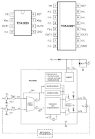
schematic diagram of light position controller which is a monolithic integrated circuit often used in passenger cars. The potentiometer in the dashboard is used to define the light beam’s elevation of the car’s headlight to a state be the car driver.
Labels:
CONTROLLER,
CONTROLLER DESIGN,
CONTROLLER GRAPHIC,
ELECTRICAL LIGHT,
LIGHT ELECTRONIC,
LIGHT POSITION
ADJUSTABLE 1.5A STEP DOWN 1.5MHz SWITCHING REGULATOR ELECTRONIC DIAGRAM
ADJUSTABLE 1.5A STEP DOWN 1.5MHz SWITCHING REGULATOR ELECTRONIC DIAGRAM
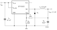
However, an Adjustable 1.5A Step Down 1.5 MHz switching regulator circuit can also be used to overcome such problem. It uses ST1S03 step down DC-DC converter. The ST1S03 can also be used to power low-voltage digital core in HDD application .
With input voltage range 3V to 16V, the ST1S03 can gives current up to 1.5A. The circuit can use tiny surface-mount components due to an high switching frequency (1.5 MHz). Resistor divider is used to set the output voltage value. Components needed to build the divided are capacitors (2 pieces), schottky diode (1 piece), and inductor (1 piece).
Labels:
RANGKAIAN SWITC,
REGULATOR,
SWITC,
SWITC CIRCUIT,
SWITC DIAGRAM,
SWITC SCHEMATIC,
SWITCH REGULATOR
5V DC REGULATED PHONE CHARGER ELECTRONIC DIAGRAM
5V DC REGULATED PHONE CHARGER ELECTRONIC DIAGRAM
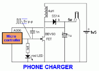
Regulated phone charger which is used as an emergency charger for mobile phones with source from ordinary batteries, and works with 1.5V input DC voltage. At 5V, it can provide output to 70mA. If the current is drawn, the voltage will be drop. A006 microcontroller is used to create square wave which used to drive the Field Effect Transistor BBV93.
Labels:
CHARGER,
CHARGER CIRCUIT,
CHARGER DIAGRAM,
CHARGER SCHEMATIC,
PHONE,
PHONE CIRCUIT,
PHONE DIAGRAM,
PHONE SCHEMATIC
Thursday, September 22, 2011
PRECISION POWER REGULATOR ELECTRONIC DIAGRAM
PRECISION POWER REGULATOR ELECTRONIC DIAGRAM
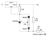
A precision voltage source is quite easy, except when the voltage should be consistent over wide range of ambient temperature. This requirement might be needed in high precision measurement system environment. For example, to provide reference voltage in analog to digital conversion.
Labels:
POWER REGULATOR,
POWER REGULATOR CIRCUIT,
POWER REGULATOR DESIGN,
POWER REGULATOR DIAGRAM,
POWER REGULATOR GRAPHIC,
POWER REGULATOR SCHEMATIC,
RANGKAIAN POWER REGULATOR,
REGULATOR
Li-Ion DRIVER WITH EXTERNAL PWM DIMMING ELECTRONIC DIAGRAM
Li-Ion DRIVER WITH EXTERNAL PWM DIMMING ELECTRONIC DIAGRAM
This boost converter is quite useful to improve conversion efficiency, reduce output ripple, and the use of small external components. In default, the LED current is set with external sensor resistor Rset, feed back voltage is regulated to 2000 miliVolts. During the operation, the current LED can be controlled using 1-wire digital interface through CTRL pin or with PWM signal that applied to the CTRL pin through the duty cycle. It determines the feedback reference voltage. The device also has a feature of integrated open LED protection that will disable the boost converter, this is to prevent the output from exceeding the absolute maximum ratings during open LED condition.
- L1: Murata LQH3NPN100NM0
- C1: Murata GRM188R61A105K
- C2: Murata GRM188R61E474K
- D1: ONsemi MBR0540T1
Labels:
Li-Ion,
Li-Ion CIRCUIT,
Li-Ion DIAGRAM,
Li-Ion DRIVER,
Li-Ion SCHEMATIC,
PWM,
PWM CIRCUIT,
RANGKAIAN Li-Ion,
RANGKAIAN PWM
AUTOMATIC AIRFLOW DETECTOR ELECTRONIC DIAGRAM
AUTOMATIC AIRFLOW DETECTOR ELECTRONIC DIAGRAM
Sensor used in this circuit is a bulb filament. If there is no airflow, the filament resistance would give low value. On the other hand, if there is airflow, the filament resistance would varies. The variation of the resistance is caused by the heat difference between filament. It also effects to the voltage variation passing through that filament. That voltage difference will be processed by LM339 op-amp and displayed by the LED.
Parts list :
- LED1 : LED 5mm
- IC1 volt regulator : LM7805
- Polar Capacitor C1 : 47 uF/15V
- Resistor R1 : 100 ohm
- Resistor R2 : 470 ohm
- Resistor R3 : 10k ohm
- Potensiometer R4 : 100k ohm
- Resistor R5 : 1k ohm
- IC2 op-amp : LM339
- Bulb filament
- Power supply/battery 12V
Labels:
AUTOMATIC DETECTOR,
DETECTOR,
DETECTOR CIRCUIT,
DETECTOR DIAGRAM,
DETECTOR OTOMATIS,
DETECTOR SCHEMATIC,
RANGKAIAN DETECTOR
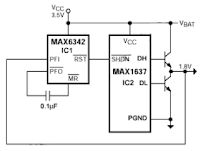
AUTO RETRY fOR MAX1637 STEP-DOWN CONTROLLER ELECTRONIC DIAGRAM
AUTO RETRY fOR MAX1637 STEP-DOWN CONTROLLER ELECTRONIC DIAGRAM
On microprocessor supervisor (IC1), an internal power-fail comparator and manual-reset circuitry (MR) is included. IC1's PFI input will detect when Vout(1.8V) is above the internal reference voltage (1.25V). Active-low RESET and active-low SHDN go high after a timeout delay of 140ms, re-enabling IC2. The other way to re-enabling IC2 is when the supply voltage is first switched on : the 3.5V rail stabilizes after 140ms will cause active-low RST to go high and activate IC2.The active-low PFO output produces a pulse using the internal 60k pull-up resistor and external 0.1 uF capacitor if Vout falls below 1.25V (due to a short circuit, for instance).
Labels:
CONTROLLER,
CONTROLLER CIRCUIT,
CONTROLLER DIAGRAM,
CONTROLLER SCHEMATIC,
ELECTRIC CONTROLLER,
RANGKAIAN CONTROLLER,
STEP-DOWN,
STEP-DOWN CONTROLLER
3V DC to 5V DC REGULATED POWER SUPPLY ELECTRONIC DIAGRAM
3V DC to 5V DC REGULATED POWER SUPPLY ELECTRONIC DIAGRAM
A 5V DC regulated output from 2 cells 3V DC batteries. The output current of the circuit is limited to 50mA. However, it still able to supply many microcontroller circuits. 3009 and 560R Resistor provide the 5V DC output, make up a voltage divider network.
Labels:
POWER,
POWER SUPPLY,
POWER SUPPLY CIRCUIT,
POWER SUPPLY DIAGRAM,
POWER SUPPLY SCHEMATIC,
RANGKAIAN POWER SUPPLY,
REGULATOR,
REGULATOR 3V,
REGULATOR 5V
CAPACITANCE METER ELECTRONIC DIAGRAM
The Capacitance Meter Circuit, However, when finished, you will have an instrument capable of measuring all but the largest capacitors used in radio circuits. Unlike variable resistors, most variable capacitors are not marked with their values. As well, the markings of capacitors from salvaged equipment often rub off.
Continue read[...]
Labels:
CAPACITANCE METER,
CAPACITANCE METER CIRCUIT,
CAPACITANCE METER DESIGN,
CAPACITANCE METER DIAGRAM,
CAPACITANCE METER SCHEMATIC,
RANGKAIAN CAPACITANCE METER,
SKEMA CAPACITANCE METER
AUTOMATIC INTRUDER ALARM ELECTRONIC DIAGRAM
A timed Bell/Siren Cut-Off. It’s designed to be used with the usual types of normally-closed input devices such as – magnetic reed contacts – micro switches – foil tape – and PIRs.
Continue read[...]
Labels:
ALARM,
ALARM DESIGN,
ALARM RUMAH,
BEL RUMAH,
BELL,
HOME ALARM
AUDIO LEVEL METER ELECTRONIC DIAGRAM
AUDIO LEVEL METER ELECTRONIC DIAGRAM
It consists of only few components. IC LM3915 converts the audio analog voltage and display it to the LED. Here is the schematic :
Parts list :
- Resistor R1 : 1k2
- Resistor variable R2 : 10k
- IC : LM3915
- LED indicator LED1-LED10 : LED 5mm
- 12V power supply
AUDIO FREQUENCY LIGHT MODULATOR ELECTRONIC DIAGRAM
AUDIO FREQUENCY LIGHT MODULATOR ELECTRONIC DIAGRAM
Light has function to replace cable from audio source to speaker. Transformer X2 is utilized to lock the audio signal. VR1 works as the amplitudo modulator from the T1 signal output.
Parts list :
- Resistor R1: 47k ohm
- Resistor R2 : 22k ohm
- Resistor R3 : 220 ohm
- Diode D1-D7 : 1N4001
- VR1 : 1k ohm
- Polar capacitor C1 : 470 uF/25V
- Polar capacitor C2 : 1 uF
- Capacitor C3 : 0.1 uF
- Transistor T1-T2 : BC148
- Transformer X1 : 220 V AC/0-12V AC
- X2 : AF output
- Transistor SCR1-SCR2 : BA654
Labels:
AUDIO,
AUDIO CIRCUIT,
AUDIO DIAGRAM,
AUDIO SCHEMATIC,
MODULATOR,
MODULATOR CIRCUIT,
MODULATOR SCHEMATIC,
RANGKAIAN AUDIO,
RANGKAIAN MODULATOR
BURGLAR ALARM USING IC TIMER 555/556 ELECTRONIC DIAGRAM
BURGLAR ALARM USING IC TIMER 555/556 ELECTRONIC DIAGRAM
circuit diagram of burglar alarm using IC timer 555/556 is functioned as an alarm to prevent thief entering your house. The alarm would produce loud sound when a thin wire connecting resistor R1 with IC pin no 4 is broken. Thin fiber is used as the wire. The thinner the wire, the more responsive the alarm. This circuit needs 5-15V power supply, buzzer is used as a speaker. Here is the circuit schematic :
Parts list :
- Resistor R1 : 10k
- Resistor R2 : 68k
- Resistor R3 : 1k
- Polar capacitor C1 : 1uF/15 B
- Capacitor C2-C3 : 0.01uF
- IC Timer : NE555
Labels:
ALARM,
ALARM CIRCUIT,
ALARM DIAGRAM,
ALARM SCHEMATIC,
BURGLAR ALARM,
RANGKAIAN ALARM,
RANGKAIAN TIMER,
TIMER,
TIMER CIRCUIT,
TIMER SCHEMATIC
Wednesday, September 21, 2011
ALTERNATING FLASHER ELECTRONIC DIAGRAM
ALTERNATING FLASHER ELECTRONIC DIAGRAM
The first IC used as a 1 second clock, which generates ON/OFF for the other ICs. Diodes help to cover the IC555 from the peak voltage. Take note that the relay used should have impedance more than 50 ohm.
Parts list :
- Diode D1-D2 : 1N4001
- Zener Diode D2 : 6V
- R1,R5,R7 : 3k3
- R2,R6,R8 : 68k
- Resistor variable VR1 : 47k
- Polar capacitor C1 : 10uF/16V
- Polar capacitor C3,C5 : 2.2 uF/16V
- Capacitor C2,C4,C6 : 0.01 uF
- Transistor T1 : BC107/BC148
- IC timer : NE555
- Relay : 6-9 V
- Power supply 6-9 V
Labels:
CAPACITOR,
DIODE,
FLASHER,
FLASHER DIAGRAM,
FLASHER ELECTRONIC,
FLASHER SCHEMATIC,
RANGKAIAN FLASHER,
RESISTOR
CAR AIR CONDITIONING ELECTRONIC DIAGRAM
CAR AIR CONDITIONING ELECTRONIC DIAGRAM
It shows the connection and wiring between each parts and component of Air Conditioning system of the vehicle such as the junction block, blower motor relay, blower resistor, blower switch, air conditioning switch, air conditioning control unit, air inlet sensor, air thermo sensor, engine control module, air conditioning engine coolant temperature switch, interior light system, dual pressure switch, heat control illumination light, interior lights system, air conditioning compressor magnetic clutch, condenser fan motor relay, relay box, and many more.
Labels:
AIR CONDITIONING,
AIR CONDITIONING CIRCUIT,
AIR CONDITIONING DIAGRAM,
AIR CONDITIONING SCHEMATIC,
CAR AIR CONDITIONING,
HOME AIR CONDITIONING,
HOTEL AIR CONDITIONING,
ROOM AIR CONDITIONING
VW CAR PASSAT ENGINE CONTROL AND AUTOMATIC SOLENOID ELECTRICAL WIRING CIRCUIT
VW CAR PASSAT ENGINE CONTROL AND AUTOMATIC SOLENOID ELECTRICAL WIRING CIRCUIT
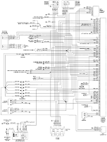
1993 VW Passat Engine Control Module, Automatic Control Unit, and Automatic Solenoid Electrical Wiring Diagram are shown in the following figure. It shows the connection and wiring between each parts and component of Engine Control Module, Automatic Control Unit, and Automatic Solenoid system of the vehicle such as the multi-function switch, fuse/relay panel, knock sensor, coolant temperature sensor, shift lock solenoid, starter interlock/back up lit relay,automatic control computer clutch shut off relay, automatic control unit, automatic solenoids, program switch, throttle position sensor, full throttle switch, idle switch, throttle valve potentiometer, ignition booster, distributor firing order, engine control module, carbon canister, cold starter, idle air control valve, evap emission on/off valve, and many more.
Labels:
AUTOMATIC CONTROL UNIT,
AUTOMATIC SOLENOID,
CONTROL MODULE,
SOLENOID CIRCUIR,
SOLENOID DIAGRAM,
SOLENOID SCHEMATIC
VW CAR PASSAT ENGINE ELECTRICAL WIRING CIRCUIT
VW CAR PASSAT ENGINE ELECTRICAL WIRING CIRCUIT
VW Passat wiring diagram are shown in the following figure. It shows the connection and wiring between each parts and component of engine compartment and headlights system of the vehicle such as the anti theft control unit, fuse/relay panel, headlight, battery, starter, alternator, starter interlock relay, warning indicators, cruise control switch, horns, clutch pedal switch, vacuum pump motor, cruise control unit, radiator cooling fan thermo switch, radiator cooling fan control unit, radiator fan motor, third speed coolant fan thermo switch, after run cooling fan thermo switch, and many more.
Labels:
CAR,
CAR CIRCUIT,
CAR DIAGRAM,
CAR ELECTRONIC,
CAR ENGINE,
CAR MATIC,
CAR PASSAT,
CAR SCHEMATIC,
ELECTRICAL,
ENGINE,
PASSAT
HONDA CB450T ELECTRICAL WIRING CIRCUIT
HONDA CB450T ELECTRICAL WIRING CIRCUIT
Honda Motorcycle parts such as the turn signal light right front, turn signal indicator, oil pressure warning light, high beam warning lamp, speedometer light, headlight, tachometer light, neutral indicator light, turn signal light left front, ignition switch, turn signal switch, dimmer switch, clutch operated switch, horn button, horn, oil pressure switch, alternator, rectifier with regulator, rectifier, starter motor, starter magnetic switch, battery, turn signal left right rear, tail and brake light, turn signal light right rear, turn signal relay, neutral switch, capacitor discharge ignition unit, rear brake light switch, ignition coil, spark plug, front brake light switch, starter switch, engine stop switch, and many more, including color codes and diagram key.
Labels:
ELECTRICAL,
ELECTRICAL CIRCUIT,
Honda,
HONDA CIRCUIT,
HONDA DIAGRAM,
HONDA SCHEMATIC,
motorcycle,
MOTORCYCLE CIRCUIT,
MOTORCYCLE DIAGRAM,
MOTORCYCLE SCHEMATIC
30W GUITAR AMPLIFIER ELECTRONIC DIAGRAM
Labels:
AMPLIFIER,
GUITAR,
GUITAR CIRCUIT,
GUITAR DIAGRAM,
GUITAR EFEK,
GUITAR EFFECT,
GUITAR ELECTRIC,
GUITAR SCHEMATIC,
SUARA GUITAR
5V DC wITH 3-pin REGULATOR ELECTRONIC DIAGRAM
5V DC wITH 3-pin REGULATOR ELECTRONIC DIAGRAM
These components usually provide very low ripple output. There are three types of 7805 components that can provide different current and power. They called linear regulators and drop minimum about 4V across themselves.
Labels:
RANGKAIAN REGULATOR,
REGULATOR,
REGULATOR CIRCUIT,
REGULATOR DC,
REGULATOR DIAGRAM,
REGULATOR ELECTRONIC,
REGULATOR GADGET,
REGULATOR SCHEMATIC,
SOFTWARE,
SOFTWARE REGULATOR
1.5V POWERED LED FLASHER ELECTRONIC DIAGRAM
1.5V POWERED LED FLASHER ELECTRONIC DIAGRAM
It is a charge pump design. This is where a capacitor (electrolytic) is allowed to charge and is then raised higher and allowed to discharge into a load. The load sees a voltage that can be higher than the supply.
Labels:
FLASHER,
FLASHER CIRCUIT,
LAMPU LED,
LED,
LED CIRCUIT,
LED DIAGRAM,
LED LIGHT,
LED SCHEMATIC,
LED WIRING,
RANGKAIAN LED
Subscribe to:
Comments (Atom)


